
Sport C Racing Tohatsu M40C Motor Rebuild
Motor Rebuild (Assembly)
This is not necessarily the right method to assemble any 2-stroke, especially a race outboard. This is my build of a moderately worn block and new-used pistons. Always refer to your engine's factory service manual for torque settings, clearance tolerances, and other vital information. Motors built for a specific mission, such as racing, may also require machining to the edge or even beyond factory specs. The values I used are probably not ideal for this motor, or for any particular application. Typical rebuild cause is a motor that was improperly broken in when new, excessive compression loss due to ring wear, cylinder scoring from; running hot/overheating, insufficient oil ratio, dust and debris entering through the carb, digesting steel OEM reeds, a burned piston from excessive ignition timing or low octane fuel, or any similar issue resulting in lose of power or compression. If you are grinding to correct the cast passageway to steel liner mismatch, it is also a good idea to re-ring (which also requires a quick hone job to establish a fresh crosshatch).
|
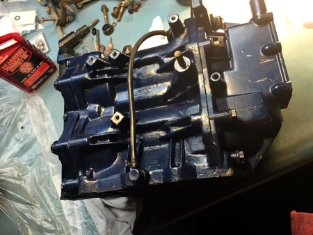
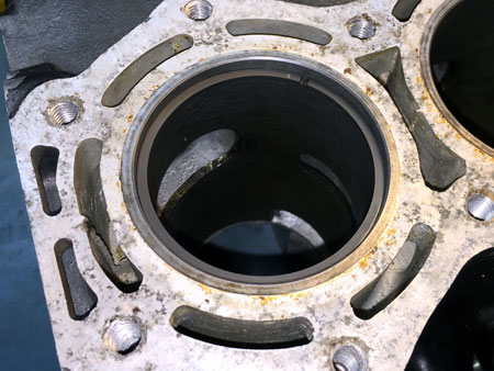
There are several varities of the Nissan/Tohatsu 40C blocks. The early models were blue or grey. A slightly revised block was brought out as the Nissan NS40C2 in late years, and painted black. In the middle years the ignition system was converted from a module with integrated coil, to an ignition box and external coil. Late model flywheels and under flywheel electrics were also slightly different. Both are compatible with all years, though the flywheel and electrics must be swapped as a pair due to clearance height changes. All the blocks were manufactured with machined port windows. Passageways cast in the blocks, particulary the boost port, were done to marginal tolerances. Nearly always the port was pressed in with a twist misalignment or undersized cast passageways. Use a die grinder or similar and relieve the overhanging aluminum casting material in the block. Don't cut into the steel liner port windows unless you know how to blueprint these motors within the rules. It is sometimes possible to slightly deck the block or head to deal with gouging from improperly removing a gasket. Again this should only be done by someone with extensive maching capability and knowledge of the stock racing rules and spec sheets. Very little material removal can fail an engine inspection on block height, quench thickness, or head chamber volume. Study the APBA Sport C Motor Specs for more information. Start with a fresh crosshatch on the cylinder bores. Make sure the block is THOROUGHLY cleaned. This means scrubbing with soapy water after boring. Drying, wiping down with WD40 or similar to prevent instant rust (steel liner), and wiping with a clean cloth to verify it is actually clean. On 2-strokes it is also imperative to chamfer the ports. Boring, often even light honing to establish a crosshatch, will remove the chamfers. Without chamfers the rings will snag, break, and trash the bores and pistons. In my case light vertical scoring is still evident. I did not want to bore for oversized pistons (time and $ restraints) so I was willing to live with the light remaining scores. I could not machine out any farther to remove the scores without exceeding the appropriate piston-cylinder clearance. OEM assembly tends to be on the tighter side of the service manual specified clearance. Tighter tolerances tend to result in a closer piston-bore fit and higher compression, however racing may need a greater clearance to prevent seizing in some cases. Always have your bore honed to match your ACTUAL pistons. Never guess, individual pistion dimensions can vary significantly. Before starting assembly I like to chase all the major bolt threads with a tap. That way they are all clean and true, particulary if heat and an impact wrench were necessary during disassembly. I finish by blowing out each hole with an air nozzle. |
 |
 |
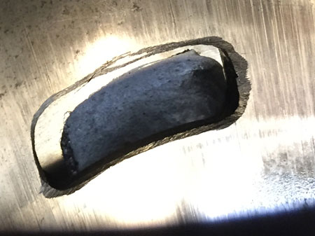
Unpack your fresh set of piston rings, but make sure to keep track of upper vs lower. They will nearly always be different. Referencing the part numbers and your service manual or parts list should identify which is which. |
|
 |
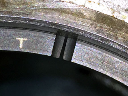
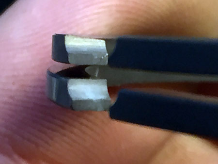
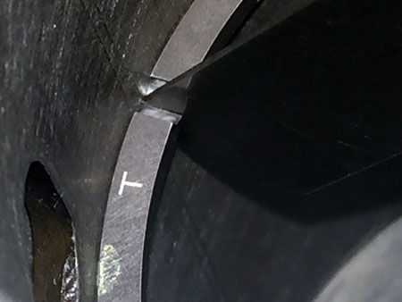
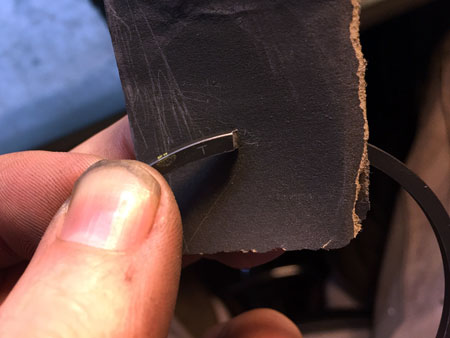
With the Tohatsu M40C (or Nissan NS40c and NS40C2) the upper piston ring is a Keystone variety, and the lower ring is a more square shape. Comparing the two it is subtle but should be obvious. Make sure to gap them for their proper position, and that they are installed in the right order on the piston. Before gapping the rings I cleaned them with a little denatured alcohol and a lint free rag. Some rings have a little protective oil on them during storage and shipping. Don't want any of that residue in the clean bore, or affecting the fitment and end gap. Start with the top piston ring. Identify which side goes towards the cylinder head. Typically this is identified with a stamped or painted mark. In this case with a "T". The ring notch will also match the orientation. Compare to the piston groove pin location if needed. |
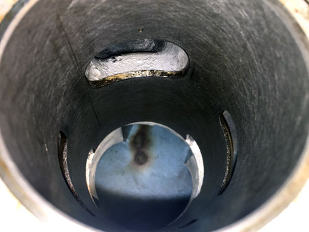
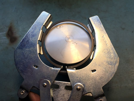
 In the image note the "T" if facing up, as well as the notches in the ring ends. Start with the ring near the top of the bore. Use feeler gauges to measure the gap. The proper size gauge should slide in with light resistance. Write down the measurement. Pull out your service manual and compare it to the measured end gap. A larger gap may be acceptable, a smaller one is never allowed. |
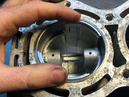
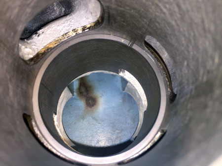
Press the ring into the cylinder, with the end gap oriented in the approximate location it will ride. Use an inverted pistion to slide the ring in squarely. If you have not already, make sure there is not a ridge in the top of the cylinder bore. Simply flex honing a used cylinder may leave a ridge at the top. It should be removed with a "ridge reamer". Any professionally bored cylinder should not have a ridge present. If the ridge is left, and the piston groove location, wrist pin bore, or any other dimension changes enough to affect the TDC ring location even slightly, the ridge will destroy the ring.
|
 |
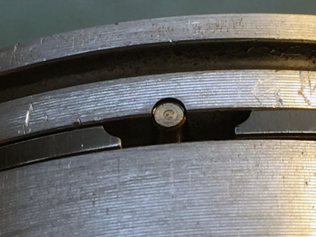
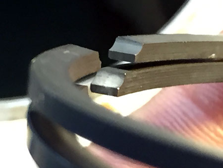
A typical minimum upper ring end gap is 0.004" per 1" of cylinder bore. In this case the Tohatsu bore is 2.76", so the minimum gap should be 0.011" (11 thousandths). My new ring measured 0.007" out of the box. Run as-is will destroy the ring, bore, and possibly piston within a few minutes. As the ring heats and expands the ends will touch, forcing the ring into the cylinder. This will score the cylinder deeply, eat away the ring, and the cylinder scoring will likely also score and destroy the piston. I picked a target end gap of no tighter than .012-.013"" at any point in the bore (top or bottom). My Tohatsu service manual stated less was acceptable, but I didn't feel comfortable deviating from the .003/1 guideline. Don't go filing away on the ring just yet. First check the gap at the bottom of the bore also. This may not be the actual bottom of the cylinder, but the lowest point at which the ring will ever be. Again use a pistoin to slide the ring down the bore squarely. |
 |
Again make sure the ring is oriented up, and with the end gap around the same position it will run as indexed by the piston groove pin. |
 |
After recording and comparing the ring end gap at the upper and lower bore positions, decide how much to file off. They make ring filling tools that will keep the ends square to each other. That doesn't mean it can't be done by hand, however, keeping the ends straight and square is difficult if not impossible. When pinched together the ends should mate up with each other without showing any light through at the inside or outside. Viewed from the side they should also be mate up. When the top ring gap is all set repeat for the lower ring. Note: the lower ring gap should be set somewhat larger than the upper. This helps prevent blowby from being trapped between the upper and lower rings causing chatter and other issues. There is discussion to what this gap difference should be. 4-stroke, 2-stroke, bore and ring material, all are reported to require different values of one opinion or another. |
When I finished filing and fitting my rings I cleaned the edges with fine sand paper. I felt like there were a few tiny burrs left from the filing process. I also wiped the rings with alcohol again to remove filing and sanding grit. After that each ring was re-measured to ensure all the gaps were correct. (don't forget, undersizing the gap will result in trashing the cylinder). Next the rings should be installed on the pistons. Do NOT oil the rings before installation. Oil will cause them to stick or carbon up in the ring groove. Use a quality ring expander. Corkscrewing rings on by hand will stretch and distort them. Cheap expanders may work, but a small engine type that supports the ring is still cheaper than a set of rings. |
 |
I install the lower ring first, followed by the upper. Make sure to orient the groove pin and ring notch. The ring should slide fully into the groove all the way around, without binding or sticking out from the piston. If it won't fully seat the groove must be cleaned. Otherwise the ring will bind up and score the cylinder.
|
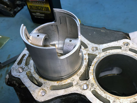
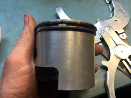
Now the piston and ring assembly is all set to be installed on the connecting rods. Note the "UP" marking on the pistion tops. This should be towards the flywheel end of the crank. Installing them upside down will index the ring ends in front of the ports, breaking the rings with the first revolution of the motor. |
 |
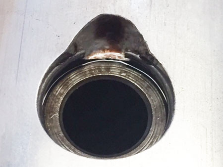
Lightly oil the piston pin and bearing. Use a suitably sized deep socket and some hand pressure to push in each pin. Be careful the pin is fully aligned with the piston before using force. If removing existing pistons, it may be necesary to tap with a rubber mallet to get them started out. Always keep track of which pin goes with which bearing and connecting rod if reusing the bearing and pin (as is common). MAKE SURE to install new clips, and orient them with the opening upward. Otherwise vertical forces will force the clip open and closed and it may come out of the groove at high RPM. A popped clip means a trashed powerhead.
|
Wipe a LITTLE oil on the piston skirts. Some builders apply a little oil to the cylinder bores as well. Others feel breakin happens faster assembling with the bores dry. Slide the pistons into the block from the bottom. Make sure the ring ends align with the indexing pins in the grooves. The assembly should drop in easily. Anything more than a gentle wiggle and something isn't lining up. As the crank nears the block the bearings and seals must be lined in. There are holes in the mid and lower bearing shell which must drop onto pins pressed into the main block half. There are also pin notches machined in the front block half for the upper bearing and mid labrynth seal. Make sure the pins are on the proper side. There are steel rings on either end of the crank which must also drop into a groove.
|
 |
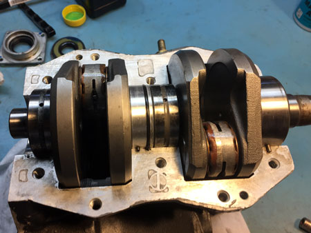 |
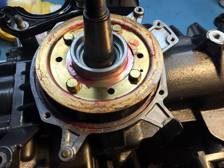
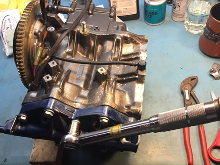
Temporarily set on the block front half to locate the bearing and crank. Then leave the crank in place but remove the block half. With everything down and seated the crank must spin easily. Pay particular attention to the counterweight connecting rod areas. If the crank is located too far up or down it may strike the block. This could require re-shimming the top bearing to adjust the crank. Sometimes there is also a tad bit of play in the locating groove and the crank can be shuffled up or down a couple thousandths. When it all feels good it's time to seal and bolt. If you haven't already, slide the bottom seal on the crank. |
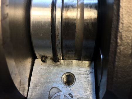
 Correct upper bearing pin location. Also note steel ring in groove. |
 Check all edges for clerance between the crank and block |
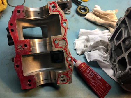 |
Apply a light coating of Loctite 518 or similar anerobic sealing compound to the front block half. Spread it in a thin layer. Drop the block half onto the rest of the assembly. It should drop down easily. Make sure the mid seal and upper bearing pins align. With hand pressure the block halves should essentially touch, any visible gap means something isn't seated. Ever plan on opening the motor up again? Get out a can of marine grade anti-seize. Brush a little on each bolt. Hand thread, noting that one is shorter and one is longer than all the rest.
|
 |
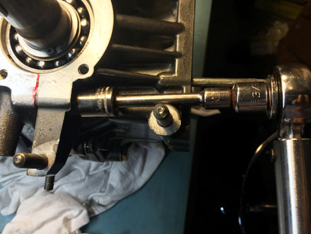
The bolts use a 13mm socket. I used a 3/8" drive torque wrench. The factory service manual gives the tightening pattern (essentially center outward). Tighten in stages, finishing at 18ft-lbs as the service manual states. A 3/8" drive socket won't fit on the two upper bolts. I used a 1/4" drive socket and extension, adapted to the 3/8" wrench. When tightening if a bolt keeps turning but won't come to torque like the others did, STOP. You may be pulling the threads out of the aluminum block. It could also be the bolt was fatigued and is stretching towards its breaking point. Remove the bolt, inspect or replace, and reattempt. Still stop if it won't come to full torque. It may be necessary to leave it slightly undertorqued to prevent pulling the aluminum block threads, or you may need to disassemble and install a helicoil or similar.
|
Support the block so the lower crank end isn't dragging on the workbench. Spin the crank by hand. There may be some resistanct but it should be smooth all the way around. I run it around a couple times and then wipe out the cylinders with a clean rag to remove any ring dust. |
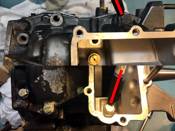
Next the Top Seal and holder goes on. The lower stator assembly plate, and stator guide plate, must also be installed at the same time. Lightly oil the top bearing and crank shaft end. Drop the seal on (make sure the seal and the housing's oring are in good shape). Then the lower stator plate sits over the crank, followed by the mounting plate and 4 bolts. Tighten with 10mm socket to the torque spec in the service manual (for M6 size bolt).
|
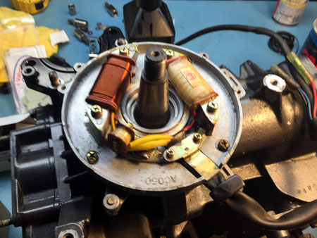 |
Now is a good time to put on the electric starter bracket. It won't fit past the flywheel, and probably won't clear the stator plate either. Grease the stator guide/mount/plate top and bottom. Add a little to the boss on the crank seal holder. Slide on the stator, line it up with the lower plate which was sitting loose on the motor. Align the 4 mount holes and tighten the phillips screws. The stator should not wiggle around much, and should spin smoothly to advance and retard timing. |
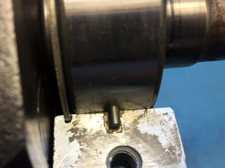
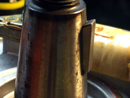
Install the flywheel key. It must be oriented as shown. The outer surface should be in line with the crank centerline, not lined up with the taper. Otherwise it will bind when mounting the flywheel. Take a look a the groove machined in the flywheel. Note that it is straight through, in line with the crank center. This is what the key must mate with, not the tapered angle of the crank end. At this point the flywheel can go on by hand. That makes it easier to spin the crank over for inspection. Sometimes I've left it off until the powerhead is on the motor. Either way the nut probably can't be torqued until the powerhead is installed. |
 |
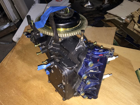
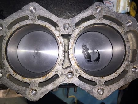
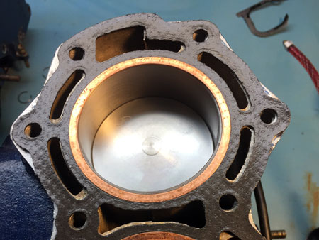
The top end should look something like this. Note the UP markings on the pistons correspond with the flywheel end. This block was corroded so the head surface isn't perfect. If you do anything to the surface, don't polish it. The gasket needs a certain amount of roughness to seal (typically factory machined to a particular finish level which leaves some milling lines and grooves). Grab the head, bolts, and some more anti-seize. Install a fresh clean gasket. Don't handle it any more than necessary. Position it flat on the block, followed by the head. Sliding things around to line them up can cut and damage the gasket. Torque the bolts in several stages, following the service manual pattern (center out). Finish around 18ft-lbs. Again note if a bolt doesn't come to torque like the rest, stop and correct the issue. |
 |
 |
 |
Main assembly finished. Ready for paint and externals. Installing the electrics, fuel pump, carb, rope starter, and linkages are pretty straightforward. I'll take some pics this spring. Also DON'T FORGET TO TORQUE THE FLYWHEEL NUT after mounting the powerhead. |
|